This diagnostic workflow is intended for heavy-duty diesel technicians, fleet maintenance teams, and parts buyers working with commercial vehicles, construction machinery, marine engines,s and generator sets. It helps separate a failed sensor from wiring, air-gap, trigger-wheel, and ECU-circuit faults before a replacement part is ordered.
Table of Contents
Key Takeaways
- No engine RPM during cranking can indicate a missing CKP signal, but it does not prove that the sensor itself has failed.
- Inductive and Hall-effect crankshaft position sensors require different test procedures.
- A resistance test alone cannot confirm that a sensor works correctly under heat, vibration, or cranking conditions.
- P0335–P0339 can be caused by the sensor, wiring, connector, air gap, reluctor wheel, or ECU input circuit.
- Match a replacement by OEM number, engine model, engine serial number, er and connector configuration—not by appearance alone.
Need a replacement CKP sensor? Volgen Power supplies OEM and heavy-duty crankshaft position sensors for Cummins, Volvo, Scania, Mercedes-Benz, and other diesel engines. Send your engine model and OEM number for a compatibility check and quotation.
What Does a Crankshaft Position Sensor Do?
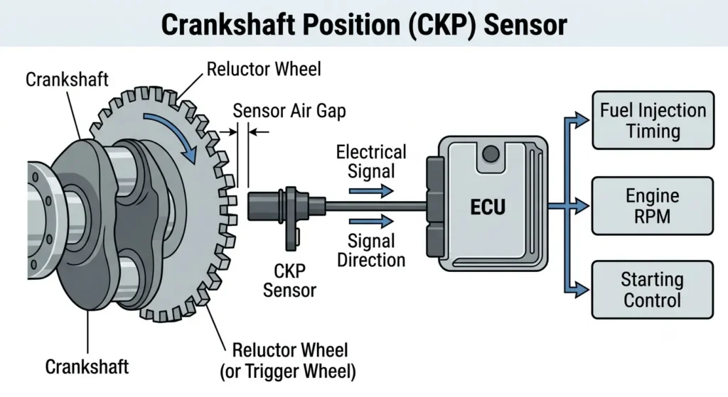
The crankshaft position sensor, commonly abbreviated as CKP sensor, monitors the rotational speed and position of the engine crankshaft. For replacement sourcing, see our heavy-duty crankshaft position sensors category.
It sends this information to the engine control unit, or ECU. The ECU uses the signal to control functions such as:
- Fuel injection timing
- Ignition timing on applicable engines
- Engine speed calculation
- Starting control
- Cylinder synchronization
- Engine protection functions
If the ECU loses the crankshaft position signal, the engine may stall, fail to start, or run incorrectly.
Important: A crankshaft position sensor fault is an electrical or signal-related problem. It does not automatically mean that the engine crankshaft itself is damaged or needs to be replaced.
Common Symptoms of a Faulty Crankshaft Position Sensor
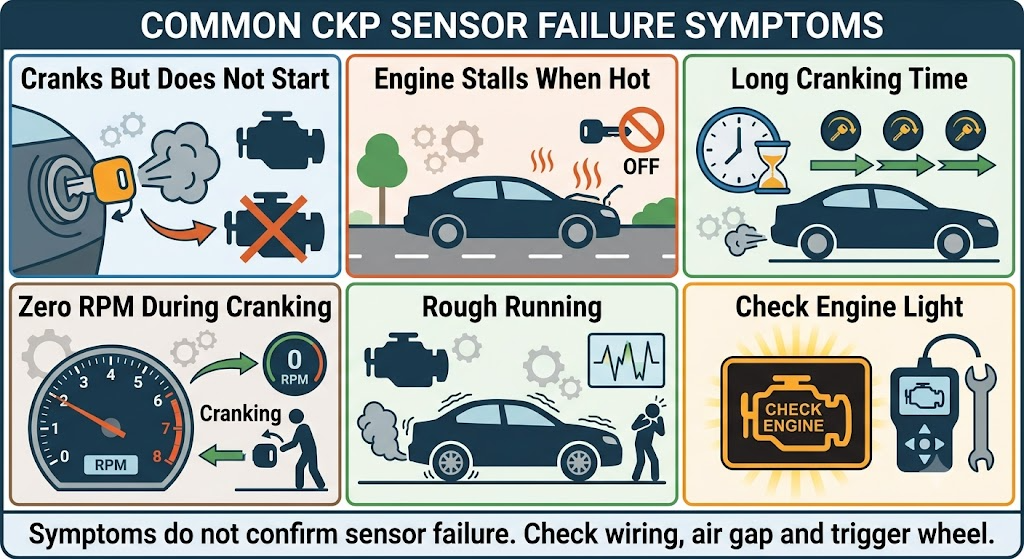
A failing crankshaft position sensor may cause several different symptoms. However, these symptoms can also be caused by damaged wiring, a weak battery, incorrect engine timing, a defective reluctor wheel, or another engine-management problem.
The sensor should therefore be tested before a replacement is ordered.
| Symptom | Possible CKP-Related Cause | What to Check First |
|---|---|---|
| Engine cranks but does not start | ECU receives no crankshaft-speed signal | Engine RPM in scan-tool live data |
| Engine stalls intermittently | Sensor signal drops out when hot or under vibration | Connector, wiring and waveform |
| Rough running or misfire | Unstable or incorrectly timed CKP signal | Fault codes and signal pattern |
| Long cranking time | Delayed crankshaft-position detection | CKP and camshaft correlation |
| Tachometer remains at zero while cranking | Missing engine-speed input | Sensor output and wiring |
| Check engine light is on | CKP circuit or correlation fault | Stored and pending trouble codes |
| Reduced engine power | ECU enters a protective operating mode | Live data and manufacturer-specific codes |
Do not replace the sensor based on symptoms alone. A complete diagnosis should include the sensor, wiring harness, connectors, trigger wheel, and ECU input circuit.
Common Crankshaft Position Sensor Fault Codes
Generic OBD-II codes associated with the crankshaft position sensor include:
| Code | General Description |
|---|---|
| P0335 | Crankshaft Position Sensor “A” Circuit Malfunction |
| P0336 | Crankshaft Position Sensor “A” Circuit Range/Performance |
| P0337 | Crankshaft Position Sensor “A” Circuit Low Input |
| P0338 | Crankshaft Position Sensor “A” Circuit High Input |
| P0339 | Crankshaft Position Sensor “A” Circuit Intermittent |
Some heavy-duty diesel engines use manufacturer-specific fault codes instead of, or in addition to, these generic codes.
A fault code identifies the affected circuit or signal. It does not necessarily mean the sensor itself has failed—record all active, stored, and pending codes before clearing them.
Inductive vs. Hall-Effect Crankshaft Position Sensors
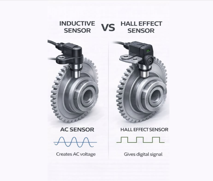
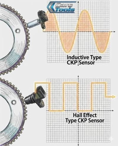
The two common CKP sensor designs are inductive sensors and Hall-effect sensors. According to Pico Automotive, a Hall-effect CKP sensor requires power and ground and produces a digital switching signal. Pico’s inductive CKP test guidance explains that an inductive sensor generates an alternating voltage whose amplitude changes with crankshaft speed.
Identifying the sensor type is essential because the testing methods are different.
| Feature | Inductive Sensor | Hall-Effect Sensor |
|---|---|---|
| Typical wiring | Usually two signal wires, sometimes with shielding | Usually power, ground and signal |
| External power supply | Normally not required | Required |
| Output signal | Analog AC waveform | Digital square-wave signal |
| Basic multimeter test | Resistance and AC output | Power, ground and signal voltage |
| Best diagnostic tool | Multimeter and oscilloscope | Multimeter and oscilloscope |
Wire count can provide a useful initial indication, but it should not be treated as final identification. Some inductive sensors include an additional shielding wire.
Use the engine wiring diagram, sensor specification, or OEM documentation to confirm the sensor type and pin assignment.
Tools Needed to Test a Crankshaft Position Sensor
Depending on the engine and sensor design, you may need:
- Compatible diagnostic scan tool
- Digital multimeter
- Automotive oscilloscope
- Back-probe leads
- Engine wiring diagram
- Manufacturer service specifications
- Basic hand tools
- Insulated gloves and eye protection
An oscilloscope is not required for every initial inspection, but it provides a much clearer view of signal quality than a digital multimeter.
Safety Precautions Before Testing
The engine may need to be cranked or operated during some tests. Follow the equipment or vehicle manufacturer’s safety procedures.
Before starting:
- Park the vehicle or equipment on a stable surface.
- Apply the parking brake.
- Place the transmission in neutral or park.
- Keep loose clothing and test leads away from belts, pulleys and rotating components.
- Do not disconnect or short ECU circuits with the ignition switched on unless the service procedure specifically requires it.
- Use the correct back-probing method to avoid damaging connector terminals.
- Do not apply external voltage to an unidentified sensor terminal.
If the wiring information is unavailable, identify the circuit before performing powered tests.
How to Test a Crankshaft Position Sensor Step by Step
Step 1: Scan the Engine Control System
Connect a compatible diagnostic scanner and check for:
- Active fault codes
- Stored fault codes
- Pending fault codes
- Freeze-frame information
- Cranking RPM
- Camshaft and crankshaft synchronization data
Record the codes before clearing anything.
Other engine faults can affect the CKP signal or produce similar symptoms. For example, low battery voltage may reduce cranking speed, while a camshaft timing fault may create a crankshaft/camshaft correlation code. If CMP-related codes are also present, compare the results with our guide to camshaft position sensor symptoms and OEM matching.
Step 2: Check Engine RPM While Cranking
Open the engine-speed parameter in the scan tool’s live-data menu and crank the engine.
If the displayed engine speed remains at zero, the ECU may not be receiving a usable CKP signal.
However, a zero RPM reading does not automatically confirm a defective sensor. Possible causes include:
- Open or shorted sensor wiring
- Corroded connector terminals
- Missing sensor power or ground
- Excessive sensor-to-trigger-wheel clearance
- Damaged reluctor wheel
- ECU connector or input-circuit problem
An unstable RPM value during cranking can also indicate an intermittent signal.
Step 3: Inspect the Sensor and Wiring
Locate the crankshaft position sensor using the service manual or engine diagram. Depending on the engine, it may be installed near the flywheel housing, crankshaft pulley, timing cover,r or engine block.
Inspect the following areas:
- Cracked or damaged sensor housing
- Loose sensor mounting
- Oil, coolant or dirt contamination
- Metal particles on the sensor tip
- Bent, loose or corroded connector terminals
- Wiring damage caused by heat or vibration
- Harness contact with sharp edges
- Incorrect sensor installation
- Damaged trigger or reluctor wheel
- Incorrect sensor air gap
Repair visible wiring or connector problems before condemning the sensor.
Step 4: Identify the Sensor Type and Terminals
Before connecting a multimeter, determine whether the sensor is inductive or Hall-effect.
Use the wiring diagram to identify:
- Sensor power supply
- Sensor ground
- Signal output
- Shielding wire, if present
- ECU terminal connections
Do not assume that all two-wire or three-wire sensors use the same pin layout.
Step 5: Test an Inductive Crankshaft Position Sensor
An inductive sensor generates its own AC signal as the reluctor wheel passes the sensor tip.
Resistance Test
Switch off the ignition and disconnect the sensor.
Set the multimeter to the resistance setting and measure across the specified sensor terminals.
Compare the result with the engine manufacturer’s specification. Different sensor designs can have significantly different resistance ranges, so a universal value should not be used.
Possible results include:
- An open-circuit reading may indicate a broken internal winding.
- A reading near zero may indicate an internal short.
- A value outside the specified range may indicate sensor damage.
- A value within specification does not guarantee that the sensor works correctly during cranking or at operating temperature.
Do not perform a resistance test on a powered circuit.
AC Output Test
If the service procedure allows it, set the multimeter to AC voltage and measure the sensor output while the engine is cranking.
The signal should be stable and should generally increase as rotational speed increases. Compare the measured output with the engine specifications.
A low or unstable output can be caused by:
- Weak sensor
- Excessive air gap
- Low cranking speed
- Damaged reluctor wheel
- Wiring resistance
- Incorrect sensor installation
Because a multimeter displays an averaged value, it may not reveal individual missing or distorted pulses.
Step 6: Test a Hall-Effect Crankshaft Position Sensor
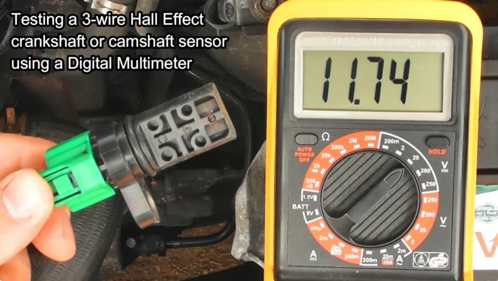
A Hall-effect sensor normally requires a power supply and ground from the engine control system.
Keep the connector attached and use the correct back-probing procedure.
Check the Power Supply
Switch on the ignition and measure the voltage between the sensor’s power-supply terminal and ground.
The expected supply voltage depends on the engine-management system. Use the wiring diagram and manufacturer specification rather than assuming that every sensor uses the same voltage.
If the power supply is missing, inspect the wiring, connectors, rs and ECU supply circuit before replacing the sensor.
Check the Ground Circuit
Measure the voltage drop or continuity of the sensor ground according to the manufacturer’s procedure.
A poor ground can produce an incorrect or intermittent signal even when the sensor itself is functional.
Check the Signal Output
Back-probe the signal wire and crank the engine.
A functioning Hall-effect sensor should switch its signal as the trigger wheel rotates. A digital multimeter may show only an averaged or changing voltage, so an oscilloscope is the preferred tool for confirming the square-wave signal.
If power and ground are correct but no switching signal is present, inspect the sensor installation and trigger wheel before replacing the sensor.
Step 7: Check the Signal With an Oscilloscope
An oscilloscope allows the technician to inspect the complete CKP waveform.
A healthy inductive sensor usually produces a consistent analog waveform. A Hall-effect sensor usually produces a regular digital square-wave pattern.
Check the waveform for:
- Missing pulses
- Irregular spacing
- Excessive electrical noise
- Low signal amplitude
- Distorted waveform shape
- Intermittent signal loss
- Changes when the wiring harness is moved
- Changes as the sensor becomes warm
A repeating missing section may be a normal reference feature of the trigger wheel. Compare the waveform with the manufacturer’s example before judging it as a defect.
Irregular signals can result from the sensor, wiring, sensor air gap, or reluctor wheel. The waveform should therefore be interpreted together with the physical inspection and wiring tests.
Step 8: Check the Wiring Between the Sensor and ECU
If the sensor output is absent or abnormal, test the related wiring.
With the ignition switched off and the circuit safely isolated, check:
- Continuity between the sensor and ECU
- Short to ground
- Short to power
- Short between signal wires
- Excessive circuit resistance
- Connector terminal tension
- Shielding continuity, where applicable
Avoid forcing oversized probes into connector terminals. Damaged terminals can create a new intermittent fault after the test is completed.
Step 9: Confirm the Repair
After repairing the circuit or replacing the defective component:
- Reconnect all wiring.
- Clear the related codes with the diagnostic scanner.
- Start or crank the engine.
- Recheck engine RPM and synchronization data.
- Confirm that the CKP signal is stable.
- Follow the manufacturer’s recommended verification procedure.
- Scan the control system again to confirm that the fault does not return.
Clearing a code without correcting the cause is not a repair.
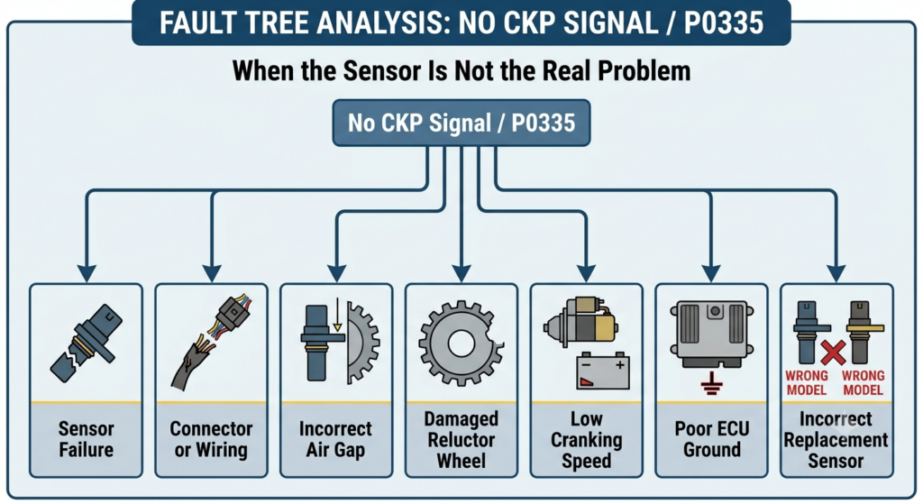
When the Sensor Is Not the Real Problem
Replacing the sensor will not solve the fault if another component is affecting the CKP signal. If you have identified the correct replacement part, contact our team with your engine model and OEM number for pricing and availability.
Damaged reluctor wheel
Bent, cracked, loose,ose or missing teeth can create an irregular signal. A reluctor wheel that has moved from its correct position can also affect engine timing information.
Incorrect sensor air gap
If the distance between the sensor and trigger wheel is too large, the signal may be weak. Contact between the sensor and trigger wheel can damage both components.
Use the specified installation depth and air gap for the engine.
Damaged wiring harness
Engine vibration, heat, oil contamination, and contact with metal brackets can damage the sensor harness. An internal wire break may only appear when the harness moves or becomes hot.
Low cranking speed
A weak battery, poor starter connection, or defective starter motor can reduce cranking speed. This may produce a weak inductive sensor signal even if the sensor is not defective.
Engine timing or correlation problem
A stretched timing chain, damaged timing gear, or incorrect timing installation can cause a crankshaft/camshaft correlation fault.
Poor engine or ECU ground
A high-resistance ground connection can interfere with sensor reference voltage and signal quality.
Incorrect replacement sensor
A sensor may look physically identical but use a different pin assignment, signal type, installation depth, or calibration. Matching by appearance alone is unreliable.
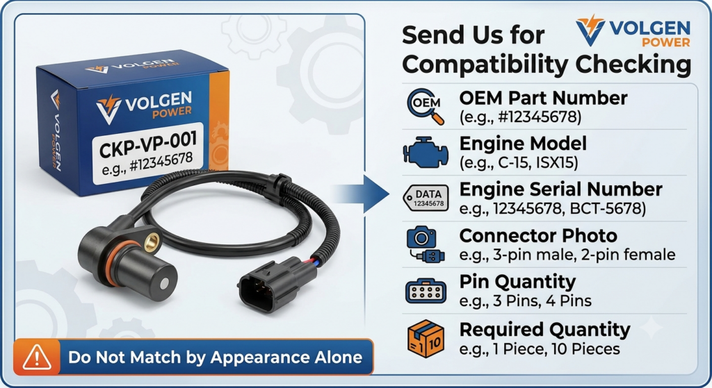
How to Match the Correct Replacement Sensor
Before ordering a crankshaft position sensor or related diesel engine component, collect the following information:
- Engine manufacturer
- Engine model
- Engine serial number
- Vehicle or equipment model
- VIN, when applicable
- Existing OEM part number
- Sensor connector photo
- Clear photo of the complete sensor
- Fault code
- Installation location
- Number of connector pins
The OEM number and engine serial number are usually more reliable than a visual comparison.
Sensors with similar housings may not be interchangeable. Differences in connector pinout, signal design, sensor length, or mounting position can prevent the engine from starting or cause repeated faults. For other heavy-duty crankshaft components and replacement parts, always verify the OEM number and engine application before ordering.
Related Products
-
Weichai 612630020038 Crankshaft
Request a Quote -
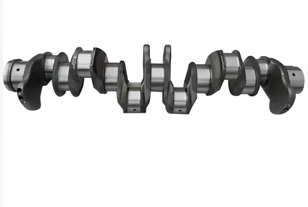
Sinotruk 201-02101-0671 Crankshaft
Request a Quote -
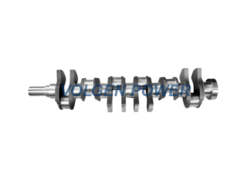
Scania OEM Crankshaft 1308467 / 312739 | Heavy-Duty Engine Part for DS11 / DSC11 Trucks
Request a Quote -
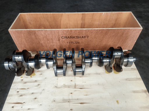
Scania DC13 Crankshaft OEM 1775228 for K N F Series Buses & Trucks
Request a Quote -
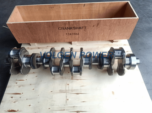
Scania DC12 Crankshaft OEM 1743584 for P G R T Series Trucks
Request a Quote -
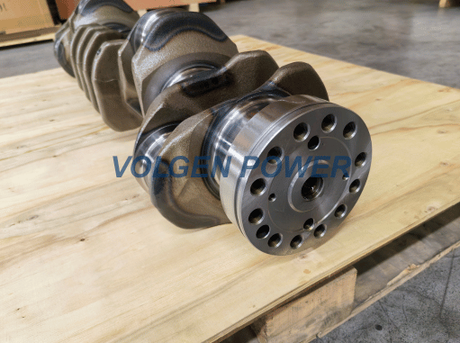
OEM Volvo 23488864 Crankshaft for D11 Engine
Request a Quote
For commercial vehicles, construction machinery, marine engines, and generator applications, confirm the engine configuration before dispatching a replacement part. Buyers sourcing Cummins diesel engine replacement parts should provide the engine serial number and existing OEM number whenever available.
Crankshaft Sensor Diagnosis Checklist
| Check | Result |
|---|---|
| Fault codes recorded before clearing | Pass / Fail |
| Cranking RPM visible in live data | Pass / Fail |
| Sensor housing and mounting inspected | Pass / Fail |
| Connector terminals inspected | Pass / Fail |
| Wiring harness inspected | Pass / Fail |
| Sensor type confirmed | Pass / Fail |
| Power and ground verified, if applicable | Pass / Fail |
| Sensor output tested | Pass / Fail |
| Reluctor wheel inspected | Pass / Fail |
| Signal compared with service specification | Pass / Fail |
| Correct OEM number confirmed | Pass / Fail |
| Repair verified and codes rechecked | Pass / Fail |
FAQs.
Can you test a crankshaft position sensor with a multimeter?
Yes. A multimeter can check resistance and AC output on some inductive sensors, or power, ground, and basic signal voltage on Hall-effect sensors. The correct procedure depends on the sensor type and engine specification. An oscilloscope provides more detailed waveform information.
Does a normal resistance reading mean the sensor is good?
No. A sensor can pass a static resistance test but fail during cranking, when hot, or under vibration. A complete diagnosis may require a dynamic output or waveform test.
Can a bad crankshaft position sensor cause a no-start condition?
Yes. If the ECU cannot detect crankshaft speed or position, it may be unable to control fuel injection and synchronization correctly. Wiring faults, low battery voltage, fuel-system problems, incorrect timing,g and reluctor-wheel damage can cause similar symptoms.
Should the sensor be replaced when code P0335 appears?
Not immediately. P0335 identifies a crankshaft position sensor circuit malfunction. Test the sensor, wiring, connector, power supply, ground, trigger wheel, el and ECU input circuit before ordering a replacement.
Are all crankshaft position sensor resistance values the same?
No. Resistance values vary by sensor design and engine application. Always use the engine manufacturer’s service specification instead of a universal resistance value.
Can a crankshaft position sensor fail only when hot?
Yes. Internal electrical faults can become more noticeable at operating temperature. If the engine stalls when hot but restarts after cooling, monitor the CKP signal and wiring during the failure.
Can a damaged reluctor wheel cause a CKP sensor code?
Yes. A damaged, loose, or incorrectly positioned reluctor wheel can distort the crankshaft-position signal. The CKP sensor reads the trigger pattern, so inspect the wheel and sensor air gap before replacing the sensor.
Technical References
- Pico Automotive: Crankshaft Position Sensor—Hall Effect, Running
- Pico Automotive: Inductive Crankshaft Position Sensor, Cranking
Need Help Identifying a Diesel Engine Part?
Correct part identification is especially important for commercial vehicles, construction machinery, marine engines,s and generator sets.
Volgen Power supplies diesel engine and transmission components for a wide range of heavy-duty applications. To request a quotation or compatibility check, send us:
- Engine brand and model
- Engine serial number
- OEM part number
- Vehicle or equipment application
- Required quantity
- Clear product and connector photos
Our team will review the available information before confirming the part application.
Send your engine model, serial number, OEM number, and required quantity to request a compatibility check and quotation.